A fully working reduced Enigma has been used very successfully in numerous public lectures, in school talks, and in university seminars. Hands-on demonstrations of the reduced Enigma dramatically brings alive ideas about design, codes, permutations and groups. As a working trapdoor function, the reduced Enigma also provides an unusually clear introduction to public key cryptography. We provide background information, lecture suggestions, and details for building it.
Full paper in Word (.doc file)
Full paper in HTML -- easier for browsing etc, but the HTML was written by Microsoft Word, so there will be formatting problems!
Harold Thimbleby is Gresham Professor of Geometry, and a Royal Society Wolfson Research Merit Award Holder. He is Director of the FIT Lab and was previously Director of UCLIC, the UCL Interaction Centre, a multidisciplinary centre at University College London. He is particularly interested in the human understanding of computers and complex systems, whether to use them more effectively and enjoyably or to understand them in a more technical sense — rather than be uncritical and passive consumers of the latest products. He gives many public and schools lectures.
See http://www.harold.thimbleby.net for more information.
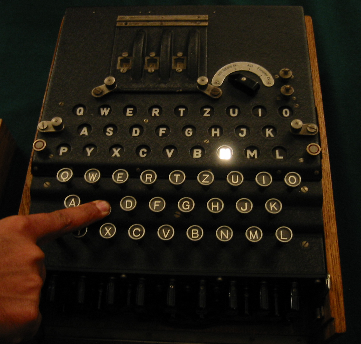
Figure 1 (jpeg) Enigma in use
Figure 2 (jpeg) Enigma rotors
Figure 3 (jpeg) Enigma plugboard
Figure 4 (jpeg) Navy manual
Figure 5 (jpeg) Reduced enigma
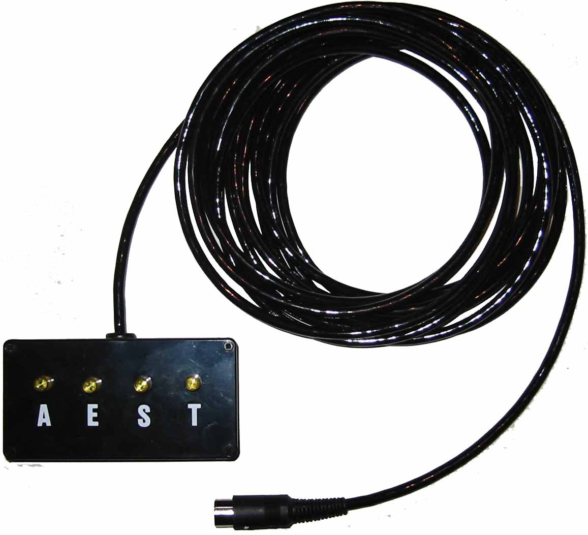
Figure 6 (jpeg) Lamp board
Figure 7 (Freehand) (EPS PostScript) Keys and lamps
Figures 8 and 9 (Freehand) (EPS PostScript) Connector wires
Figure 10 (Freehand) (EPS PostScript) Lamp board
Figure 11 (Freehand) (EPS PostScript) Rotor wiring
Figure 12 (Freehand) (EPS PostScript) Initial key setting
Figure 13 (Freehand) (EPS PostScript) Reset circuit
Figure 14 (Freehand) (EPS PostScript) Reciprocal wiring